On Load Flow Studies by Gauss-Seidel Method
| ✅ Paper Type: Free Essay | ✅ Subject: Engineering |
| ✅ Wordcount: 1805 words | ✅ Published: 18 May 2020 |
Contents
- Abstract
- Acknowledgment
- 1.Introduction
- 2. Description of Research and development of final specifications
- 2.1 Buses use in the Load flow studies
- 2.2 Classifications of buses
- 2.3 Gauss seidel Method
- 3. Design of the system
- 4. Software and Hardware Description
- 4.1 Software Description
- 4.2 Hardware Description
- 4.3 Flow chart for the Gauss-Seidel
- 4.4 Explain the Flow chart
- 4.5 Simulation Results
- 5. Conclusion
- 6. Bibliography
- 7. Appendix
- 7.1 MATLAB coding
- 7.2 Command Window Results for 1st iteration
- 7.3 Command window Results for 12th iteration
- 7.4 Budget Chart
- 7.5 Gantt-Chart
- Abstract
Technologies are putting impact on our daily life and in the industry field. Advanced power system is one of them which is further linked with Power Engineering field where researches and technical innovations are taking place. So now, in this whole project we are going to talk about the load flow studies by using Gauss-Seidel Method.
As we know, Load flow is essential tool used by power engineers to plan and to interchange power among utility firms. For getting an efficient operating power system it is utmost important that which method is appropriate and efficient for the load flow studies because we have so many methods like Newton-Raphson method, Gauss-Seidel method and fast decoupled load-flow method. In load flow firstly we have to identify the phase angle and magnitude of the voltage on every bus and real & reactive power flowing in each transmission line. This project includes introduction of the project, three buses, various steps of Gauss-Seidel method through flow chart, output of simulation and specifications of the project coding of Gauss-Seidel method with the help of Matlab software, comparison of simulation results with number of iterations.
1. Introduction
A load flow study is a steady-state analysis whose main purpose is to find the voltage magnitude, phase angle, real and reactive power in a system under given load conditions.
In the power system, the power moves from generating station to the load across many sections of the network. Power flow studies give us organised mathematical viewpoint to find out the bus voltage, reactive and active power flows between different sections, phase angles and load under stable conditions. The power system is mainly shaped by an electric circuit which contains generators, transmission networks and distribution networks.
The main purpose of load flow studies are plan forward and report for different hypothetical situations. For example:- if a transmission line is to be hold for maintenance can the remaining lines in the system handle the required loads without go beyond of their rated values.
The following are main purposes to do the load flow studies:-
- Real and reactive power flowing in every element.
- Reactive power on generator.
- Phase angle and voltage magnitude on every bus.
The above we can get if we supply the load flow programme with the following information:-
- Phase angle and voltage magnitude at one bus, which will be reference point for the whole system.
- Voltage magnitude on every generator bus and real power generation.
- Real and reactive power needed on each load bus.
- Branch list of system connections that is the impedance of each element, sending end and receiving end node.
Ref. (5)
2. Description of Research and subsequent development of final specifications
2.1 Buses use in the Load flow studies
A bus is a point which connects one or many loads, generators and transmission lines. In load flow studies every bus is linked with four variables those are phase angle of voltage(δ), active power(P), reactive power(Q) and magnitude of voltage(|V|). In which any two are specified variables and remaining two are unspecified variables.
2.2 Classifications of buses are depend upon the specified variables
1. Slack Bus:- This bus is mainly a generating unit and also known as slack bus. The specified variables on this bus are magnitude of voltage(|V|) and phase angle of voltage(δ) whereas unspecified variables are active(P) and reactive powers(Q).
2. Generator(PV) bus:- This bus is voltage control bus. This bus is at the generating unit so that by adjusting the prime movers we can control the output power generated by this bus and voltage can be controlled to adjust the excitation of generator. The known variables for this bus are P and |V| whereas unknown variables are Q and δ.
3. Load(PQ) bus:- This bus is the non-generator bus and is also known as PQ bus. In this real and reactive power supply to system are determine as positive, whereas, power consumed by the system is defined by negative. The known variables are P and Q and the unknown variables are δ and |V|.
Ref. (2)
2.3 Gauss seidel Method
Gauss seidel method is the modification of the Gauss iterative method. The number of iteration are less in Gauss seidel method as compare to Gauss ieterative method
We are using Gauss-Seidel method to solve the non-linear equation. This is very simple method and it can be used in digital computers.
V2=
1(Y22)[P2–jQ2V2*
+ V1Y21+ V3Y23]
This is my non-linear equation. We can not solve this so we used Gauss-Seidel method to solve this equation. Either we have to do a lot of iterations but we get appropriate results by Gauss-Seidel method.
Ref. (3)
3 Design of the system

3.1 Application of Gauss-seidel Method
The Gauss- Seidel method is modification of the Gauss-iteration method. This method is an iterative method used to solve the non-linear equations in power flow studies. In this method firstly we are taking the initial guesses of voltage values so that we get value of the particular variables by putting the values of initial guesses into equation . After that initial guess value is replaced by new value that we have calculated previously. The same procedure repeated again and again until iteration solution converges.
Ref. (1)
Let us understand the Gauss Seidel method:-
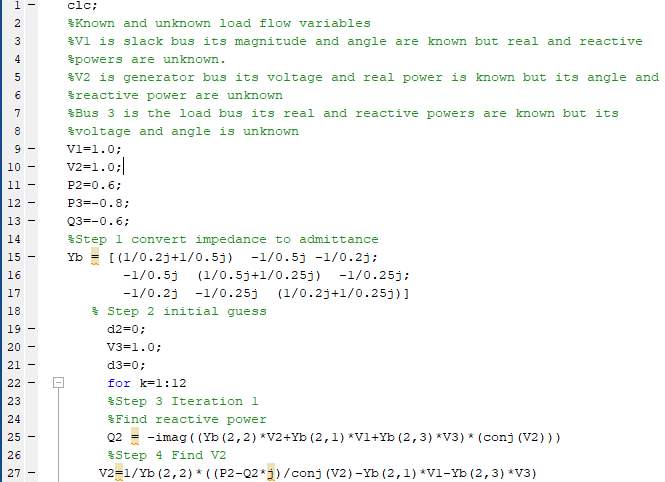
Step 1:- Make Ybus
Step 2:- Assume the Initial values(d2=0, d3=0, V3=1.0).
Step 3:- Calculate reactive power Q2 by following equation
Q2 = -imag((Yb(2,2)*V2+Yb(2,1)*V1+Yb(2,3)*V3)*(conj(V2)))
Step 4:- Calculate V2 by V2=
1(Y22)[P2–jQ2V2*
-V1Y21-V3Y23]
Step 5:- Fix the magnitude 1
Step 6:- Again recalculate the V2 and again reset.
Step 7:- Calculate V3
V3=1/Yb(3,3)*((P3-Q3*j)/conj(V3)-Yb(3,1)*V1-Yb(3,2)*V2)
and recalculate V3 and get updated value of V3
Step 8:- Repeat step 3-8 for 12 iterations.
Step 9:- End of the iterations. We are checking the results upto four decimal places if its correct then proceed further, if its not then go for more iterations.
Step 10:- Calculate power among transmission lines.
Step 11:- Calculate power at each bus.
Ref. (3)
4. Software and Hardware Description
4.1 Software Description
From last few years, many high-level programming languages like Matlab, Mathematica, Mathcad and many more have become popular for educational and research purposes.
In this power flow project we will use Matlab software because it is very difficult to solve the long iterations by hand. With this software we will do the coding of load flow. We can solve the long iterations with the help of Matlab programming it will save our time and we get correct results of our equations.
4.2 Hardware Description
Load flow studies are based on the software so there is no uses of hardware. I did not use any hardware for this project.
4.3 Flow chart for the Gauss-Seidel

Ref(3,4)
4.4 Explain the Flow chart
As we can seen from this flow chart that in the first step we have defined the Ybus elements then convert the impedance to admittance. Then in the next step we have to take some initial guesses for (d2,d3 and V3)which are phase angles of generator bus,load bus and voltage magnitude of the load bus respectively.Further, in step 3 we are going to find out the reactive power Q2 for the generator bus. In step 4 we are finding the voltage magnitude of generator bus by a equation which is V2=
1(Y22)[P2–jQ2V2*
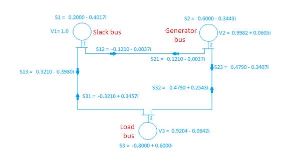
-V1Y21-V3Y23] Then we have to fix the magnitude of the output V2 because in the power station there are 3 buses slack bus, generator bus and load bus. At the generating station there are two settings that you can set.The magnetic field inside the generator for the excitation that will set the magnitude of the voltage and you can set the input from turbine that is the amount of real power coming out from the turbine but you can not set reactive power because there is no setting at generating station which control the reactive power as turbine controls the real power P. so in this step we have fix the magnitude. In next step we substitute the new value of V2 back into the equation and get the value and again fix the magnitude and get updated value of V2. Then find the V3 (magnitude voltage for the load bus). Recalculate and get the updated value of V3. After this we are checking the accuracy of the system. In my case it was not accurate in first iteration so I did 12 iterations to get accurate results. For the accuracy I have checked my values upto 4 decimal places. When I get accurate results then I have find the powers of transmission line and each bus. To find the powers I have used susceptance because as we know there is no resistance in the system so susceptance is used. When I calculate powers on the transmission lines then I have seen that in same transmission line my real power is same but reactive power is different, For instance (S13 = 0.3210 – 0.3980i , S31 = -0.3210 + 0.3457i) because line absorb some reactive power. In the final step we have find out the powers on each bus.
4.5 Simulation Results

Ref. (3)
5. Conclusion:-
Load flow studies are essential for determining the operation of the excitation system. Load flow studies give us the bus voltage magnitude and phase angle of the voltage at each bus and power flow on the transmission lines and on the buses. We can solve the non-linear equations with simple technique. With the help of Gauss-Seidel method we can get the accurate results through iterations. We can solve the load flow equations with the Matlab coding because it is very fast and we can get real and reactive power and voltage magnitude through some steps. When I did this project I get brief knowledge about the load flow studies and how can Gauss-seidel method works in the load flow studies.
6. Bibliography
- Modern Power Systems Analysis, D P Kothari and I J Nagrath
- https://circuitglobe.com/classification-of-power-system-buses.html
- Power System by Behic R. Gungor Published-Haecourt Brace Jouanovich 1/01/1998
- http://www.engineeringenotes.com/electrical-engineering/power-flow/gauss-seidel-method-for- power-flow-studies-electrical-engineering/25205
- https://www.sciencedirect.com/topics/engineering/gauss-seidel-method
7. APPENDIX
7.1 MATLAB CODING


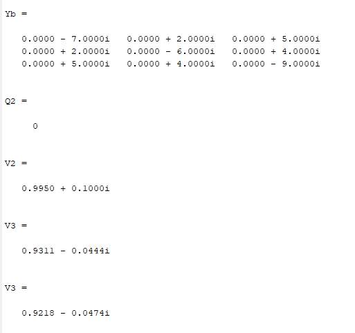
7.2 Command window results of 1st Iteration

7.3 Command window results of 12th iteration

As we can see the real part of S13 and S3 1 is same but imaginary part is different because line absorb some reactive power.


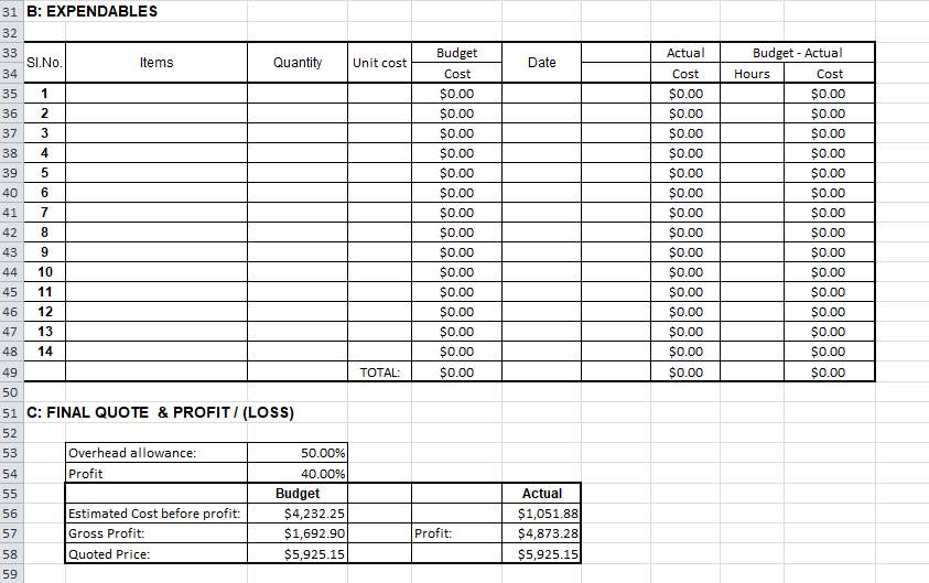
7.4 Budget Chart


7.5 Gantt-chart


Cite This Work
To export a reference to this article please select a referencing stye below:
Related Services
View allDMCA / Removal Request
If you are the original writer of this essay and no longer wish to have your work published on UKEssays.com then please click the following link to email our support team:
Request essay removal


